This is an old revision of the document!
Cisco : VLAN
VLAN (Virtual Local Area Network) adalah sebuah metode untuk membagi satu jaringan komputer fisik menjadi beberapa jaringan virtual yang terpisah. Hal ini memungkinkan Anda untuk mengelompokkan komputer berdasarkan fungsi, departemen, atau proyek—tanpa harus mengubah kabel fisik yang sudah ada.
Syntax
Membuat VLAN
| Command | Description |
|---|---|
S1(config)#vlan [vlan-ID] | Membuat VLAN baru dan menetapkan nomor VLAN |
S1(config-vlan)#name [name] | Memberikan nama pada VLAN |
Example:
vlan 10
 name VLAN-10
vlan 20
 name VLAN-20
vlan 99
 name VLAN-Management
Assigning VLAN ke Interfaces
Setelah VLAN dibuat, port switch dapat ditetapkan ke VLAN tertentu.
| Command | Description |
|---|---|
S1(config)#interface [int-id] | Masuk ke mode konfigurasi interface (gunakan interface range untuk beberapa port) |
S1(config-if)#switchport mode access | Mengatur interface ke mode access |
S1(config-if)#switchport access vlan [vlan-id] | Menetapkan interface ke VLAN tertentu |
Contoh:
interface GigabitEthernet1/0
 switchport mode access
 switchport access vlan 10

interface range GigabitEthernet2/0 - 3
 switchport mode access
 switchport access vlan 20
Menghapus VLAN
| Command | Description |
|---|---|
S1(config)#no vlan [vlan-id] | Menghapus VLAN tertentu |
S1(config)#delete flash:vlan.dat | Menghapus file database VLAN dari flash memory |
Menghapus VLAN dari Interface
| Command | Description |
|---|---|
S1(config)#interface [int-id] | Masuk ke mode konfigurasi interface |
S1(config-if)#no switchport access vlan [vlan-id] | Menghapus penugasan VLAN dari port |
“⚠️ Ketika sebuah VLAN dihapus, port yang dialokasikan ke VLAN tersebut akan menjadi tidak aktif (inactive). Namun, jika Anda menggunakan perintah no switchport access vlan [vlan-id], port tersebut akan kembali ke VLAN 1.”
Topologi
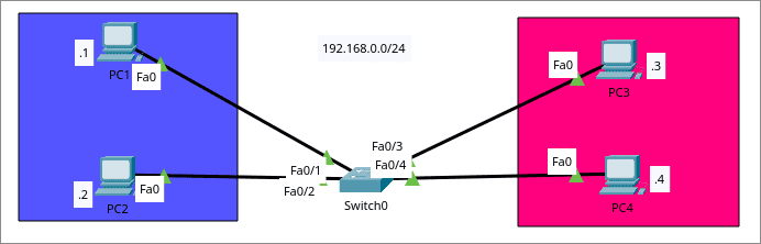 “Sebelum konfigurasi VLAN, keempat end host berada dalam LAN yang sama (192.168.0.0/24) dan dapat saling berkomunikasi. Setelah mengonfigurasi VLAN, kita akan membagi topologi tersebut menjadi dua VLAN terpisah untuk mengisolasi lalu lintas data (traffic).”
Goalsnya adalah untuk memisahkan Devices sesuai VLAN pada topology
“Sebelum konfigurasi VLAN, keempat end host berada dalam LAN yang sama (192.168.0.0/24) dan dapat saling berkomunikasi. Setelah mengonfigurasi VLAN, kita akan membagi topologi tersebut menjadi dua VLAN terpisah untuk mengisolasi lalu lintas data (traffic).”
Goalsnya adalah untuk memisahkan Devices sesuai VLAN pada topology
- VLAN 10 - PC1,PC2
- VLAN 10 - PC3,PC4
Konfigurasi
- Step 1 : Pembuatan VLANs
Switch(config)#vlan 10
Switch(config-vlan)#name BIRU
Switch(config-vlan)#exit

Switch(config)#vlan 20
Switch(config-vlan)#name MAGENTA
Switch(config-vlan)#exit
- Step 2 : Assign VLANs ke Ports
Switch(config)#interface f0/1
Switch(config-if)#switchport mode access
Switch(config-if)#switchport access vlan 10
Switch(config-if)#exit

Switch(config)#interface f0/2
Switch(config-if)#switchport mode access
Switch(config-if)#switchport access vlan 10
Switch(config-if)#exit
Dapat dapat juga menggukan interface range untuk menkongigurasi banyak interface secara bersamaan:
Switch(config)#interface range f0/3-4
Switch(config-if-range)#switchport mode access
Switch(config-if-range)#switchport access vlan 20
- Step 3 : Check VLAN Summary
Switch#show vlan brief
Sample Output:
VLAN Name                             Status    Ports
---- -------------------------------- --------- -------------------------------
1    default                          active    Fa0/5 - Fa0/24, Gig0/1, Gig0/2
10   BIRU                             active    Fa0/1, Fa0/2
20   MAGENTA                          active    Fa0/3, Fa0/4
1002 fddi-default                     active
1003 token-ring-default               active
1004 fddinet-default                  active
1005 trnet-default                    active
Tes
- PC1 → PC2,PC3,PC4
C:\>ping 192.168.0.2

Pinging 192.168.0.2 with 32 bytes of data:

Reply from 192.168.0.2: bytes=32 time<1ms TTL=128
Reply from 192.168.0.2: bytes=32 time<1ms TTL=128
Reply from 192.168.0.2: bytes=32 time<1ms TTL=128
Reply from 192.168.0.2: bytes=32 time<1ms TTL=128

Ping statistics for 192.168.0.2:
    Packets: Sent = 4, Received = 4, Lost = 0 (0% loss),
Approximate round trip times in milli-seconds:
    Minimum = 0ms, Maximum = 0ms, Average = 0ms

C:\>ping 192.168.0.3

Pinging 192.168.0.3 with 32 bytes of data:

Request timed out.
Request timed out.
Request timed out.
Request timed out.

Ping statistics for 192.168.0.3:
    Packets: Sent = 4, Received = 0, Lost = 4 (100% loss),

C:\>ping 192.168.0.4

Pinging 192.168.0.4 with 32 bytes of data:

Request timed out.
Request timed out.
Request timed out.
Request timed out.

Ping statistics for 192.168.0.4:
    Packets: Sent = 4, Received = 0, Lost = 4 (100% loss),
- PC3 > PC1,PC3,PC4
C:\>ping 192.168.0.1

Pinging 192.168.0.1 with 32 bytes of data:

Request timed out.
Request timed out.
Request timed out.
Request timed out.

Ping statistics for 192.168.0.1:
    Packets: Sent = 4, Received = 0, Lost = 4 (100% loss),

C:\>ping 192.168.0.2

Pinging 192.168.0.2 with 32 bytes of data:

Request timed out.
Request timed out.
Request timed out.
Request timed out.

Ping statistics for 192.168.0.2:
    Packets: Sent = 4, Received = 0, Lost = 4 (100% loss),

C:\>ping 192.168.0.4

Pinging 192.168.0.4 with 32 bytes of data:

Reply from 192.168.0.4: bytes=32 time<1ms TTL=128
Reply from 192.168.0.4: bytes=32 time<1ms TTL=128
Reply from 192.168.0.4: bytes=32 time<1ms TTL=128
Reply from 192.168.0.4: bytes=32 time<1ms TTL=128

Ping statistics for 192.168.0.4:
    Packets: Sent = 4, Received = 4, Lost = 0 (0% loss),
Approximate round trip times in milli-seconds:
    Minimum = 0ms, Max